Main Menu
- Home
- Product Finder
- Calibration Systems
- Calibration Services
- Digital Sensing
- Industrial Vibration Calibration
- Modal and Vibration Testing
- Non-Destructive Testing
- Sound & Vibration Rental Program
- Learn
- About Us
- Contact Us
There are two basic designs of calibration shakers: flexure-based shakers and air-bearing shakers. The names reflect the way in which the vibrating element is suspended. This difference in design also directly affects the transverse (commonly, the horizontal) motion of the vibrating element. In flexure shakers, the motion of the vibrating element is modeled very well by a classic second order system. In this model, the vibrating element acts as the mass and the flexure suspension acts as the spring. The suspension acts not only in the axial direction but also in the transverse direction. Since the transverse stiffness is not infinite, the system has a resonance in the transverse direction, and the transverse motion at this frequency causes an undesired sensor output and this error in the calibration.
Air bearing shakers do not have a mechanical flexure, and so the classic second order model does not apply as well. In fact, the springs in the flexure-based shaker have been removed and replaced with two different suspension methods: a Lorentz force coil and a forced air source. The Lorentz force coil suspends the vibrating element in the vertical direction by applying a DC current to the shaker. The vibrating armature’s lateral position is maintained by the forced air flow from the base of the shaker into and around the vibrating armature. The forces from this thin film of pressurized air, acting on the vibrating armature, keep the armature centered laterally. With the substantially higher lateral stiffness of the air bearing design, the transverse resonance seen in the flexure-based shaker design is no longer present within the operating frequency range for calibration. This results in a purer, vertical sinusoid exciting the transducers under test, which in turn results in a more precise and accurate calibration.
Next, we will discuss “How does this transverse motion cause an error in the calibration?" To answer this question, we must understand three things:
1.) The existence of the transverse motion due to the shaker (discussed above).
2.) The nature of transverse sensitivity of accelerometers.
3.) The assumptions we make when we use the back-to-back calibration method of ISO 16063-21.
Understanding the directional nature of transverse sensitivity in an accelerometer is key. Transverse sensitivity changes depending on the direction of the transverse motion. For a typical piezoelectric accelerometer, the direction of the sensitivity is shown in the polar plot below.
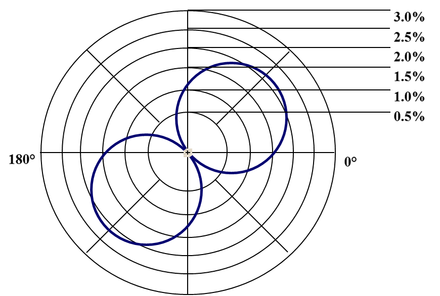
As we may see from the polar plot, the direction of maximum sensitivity is 90 degrees from the direction of minimum sensitivity.
Next, we consider the nature of an ISO 16063 back-to-back calibration. It looks like this:
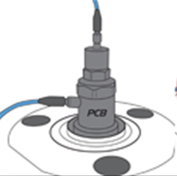
This picture shows two accelerometers mounted "back-to-back." The accelerometer on top is the accelerometer to be tested; the one on the bottom is a reference accelerometer. We will reduce the theory of this technique by just saying that it assumes both accelerometers experience the same physical vibration by mounting them directly to each other.
When these things come together, they can become problematic. Consider a calibration situation where the following things are true:
a.) The test frequency is at the transverse resonance of the shaker, causing motion in the horizontal direction that is 120% to 200%1 of the amplitude in the vertical direction.
b.) By chance, the direction of maximum transverse sensitivity of the test accelerometer is aligned with the direction of minimum transverse sensitivity of the reference accelerometer.
c.) The horizontal motion described in (a.) is in the direction described in (b.)
This would cause artificially high output of 200% x 3% = 6% in the test accelerometer signal. That is, the 200% transverse vibration level x the (previously unmentioned) 3% transverse sensitivity of the test accelerometer2. This 6% increase in test accelerometer output is enough to cause a false failure outcome of the calibration test.
So, we now understand that transverse motion effects on accelerometer calibration results are rooted in the shaker design (which causes the transverse motion), perpetuated by the accelerometer design, and left unmitigated by the ISO standard calibration technique. To reduce these effects, we must influence one of these 3 things: basic shaker design, basic accelerometer design, or the basic calibration technique.
The 2nd and 3rd items in this list are mature designs that have been refined over decades, and satisfy many other user requirements while also addressing transverse motion. Making improvements in these areas may best be described by the Italian proverb of extracting blood from a stone3. The clearest opportunity for improving the accelerometer calibration measurement is by selecting a shaker design that minimizes the transverse motion. We recommend seeking out an expert in accelerometer calibration that can help you minimize this particular component of uncertainty, as well as any other components.
1This is typical for flexure-based shakers.
2This analysis is somewhat simplified, but the results we see with flexure shakers are consistent with this analysis.
3Or perhaps we should credit the English. We won't debate that here.