Main Menu
- Home
- Product Finder
- Calibration Systems
- Calibration Services
- Digital Sensing
- Industrial Vibration Calibration
- Modal and Vibration Testing
- Non-Destructive Testing
- Sound & Vibration Rental Program
- Learn
- About Us
- Contact Us
A description of the patent-pending ICPRTM circuit must include overviews of the ICP® system, as well as bridge conditioning, since it combines elements of both.

Prior to the use of ICP®, (the original Internal Electronic PiezoElectric scheme, commonly known as IEPE), users of Piezoelectric (PE) transducers had to painstakingly maintain extremely high impedance of circuitry, insulation, and cables, in order to maintain reasonable bandwidth and signal-to-noise levels. These requirements were greatly relaxed by placing miniature electronics within the transducer, as shown above. The electronics were powered by a DC current, provided by the supply at the other end of the two-wire cable. The circuit converted signals to low impedance analog voltage riding on a DC bias level, such that supply and signal were carried on the same wire. System and cabling costs were greatly reduced, as was susceptibility to noise. The convenience and cost-effectiveness of the ICP® scheme triggered the overwhelming predominance of the ICP® interface over charge mode PE transducers.
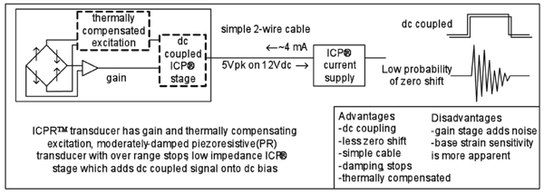
PE transducers are, as a class, extremely rugged and would otherwise be an excellent choice for shock measurement, except for the fact that they are inherently AC-coupled. As shown in figure, AC-coupled signals cannot maintain a static signal, instead the response to a square wave decays away and distorts the pulse shape. Worse, they exhibit a tendency to take on a zero-shift under certain shock conditions. Shifted output cannot be accurately integrated to get velocity and displacement, which are parameters frequently needed by users of accelerometers. Researchers found that piezoresistive (PR) sensors were less prone to zero-shift and were DC-coupled, solving both the above problems. PR sensors have therefore become the preferred sensor to use for shock measurements during long duration events, and particularly when integration was required.
But PR sensors have their own demands in conditioning and cabling, as described in the figure below. And they have their own weaknesses: particularly Micro-Electro-Mechanical Systems (MEMS) sensors, being made of single crystal silicon, can be brittle and prone to failure by resonant amplification.

With improvements, such as the low damping and stops incorporated in PCB®’s Series 3501 and Series 3991 family of MEMS sensors, the weaknesses have been largely overcome. Combining the MEMS sensor with the patent pending ICPRTM circuitry depicted in the figure below, the evolution of shock sensors ascends to its peak. The internal circuitry starts with the familiar two-wire current-driven source, then adds an excitation circuitry which compensates for the thermal sensitivity slope of PR, adds gain in an instrumentation amplifier, and translates its DC-coupled output to the ICP® bias, giving you a shock accelerometer with the best of both worlds!
