Main Menu
- Home
- Product Finder
- Calibration Systems
- Calibration Services
- Digital Sensing
- Industrial Vibration Calibration
- Modal and Vibration Testing
- Non-Destructive Testing
- Sound & Vibration Rental Program
- Learn
- About Us
- Contact Us
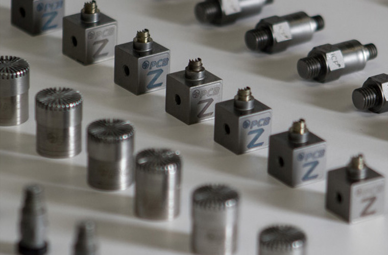 Within the world of ICP® sensing there are some common options that can be applied to almost any typical accelerometer.
Here’s a quick review of the most common options. How many of them are you familiar with? This list contains PCB® model number prefixes and a brief description of each.
Within the world of ICP® sensing there are some common options that can be applied to almost any typical accelerometer.
Here’s a quick review of the most common options. How many of them are you familiar with? This list contains PCB® model number prefixes and a brief description of each.
Transducer Electronic Data Sheet (TEDS) option, per IEEE1451.4 (2004) standard ( http://standards.ieee.org/develop/regauth/tut/), adds a small digital memory chip to the internal sensor ICP electronics to allow it to communicate information such as its model number, serial number, and calibration value to TEDS-enabled ICP sensor signal conditioners and analyzers. There are currently two sub-options within the PCB Group TEDS offerings. Remember that what version of TEDS your system can read is analyzer or software-dependent. It is best to contact and discuss this with your system vendor before choosing which format to order with your TEDS accelerometer. Please note that not all TEDS sensors include the TLD or T prefix. Always confirm TEDS details on the sensor's spec sheet. (Calibration Tip: TMS 9155 Automated Accelerometer Calibration System reads and writes all the TEDS templates linked here. If your current calibration system cannot handle TEDS, there is also a stand-alone read/write kit, TMS Model 400B76, which handles programming through a standard USB port.)
TLD = TEDS v1.0 general format is the IEEE-released format for general-purpose use, and is the default format to consider when specifying a TEDS-enabled sensor. This version writes information, including the model number, manufacturer, and serial number, permanently into the programmable “write once” section of the memory chip. The rewritable section stores data including sensitivity, calibration date, reference frequency, calibration period, sensor polarity, and mass.
T = TEDS v0.9 general format was used for a few years during the formation and balloting of the standard. The fundamental difference between this preliminary version and TEDS v1.0 is that v0.9 does NOT make use of the programmable
write once section of the memory. All data in this version is written into the programmable rewritable section of the memory.
M = Metric modifies mounting methods to an appropriate metric thread. On models with UNF 5-40 thread, the metric equivalent becomes M3 x 0.50, and on models with 10-32 thread, the metric equivalent becomes M6 x 0.75. For industrial applications, metric version accelerometers are typically M6 x 1.0. Please note that some specific model numbers (for example, PCB 340 series accelerometers) include all metric threads, hex, and connectors as standards without an “M” prefix. (Calibration Tip: Adaptors are available for the PCB/TMS model K394B30 precision air bearing calibration exciter to adapt to all common accelerometer mounting threads.)
HT = High temperature option for ICP sensor internal electronics increases the standard operating temperature from a maximum 250 degrees F (121 degrees C) to 325 degrees F (163 degrees C). For extreme temperature environments up to 900 degrees F (482 degrees C), like gas turbine vibration applications, there are special accelerometers like the PCB model EX600B13 differential accelerometer. (Calibration Tip: Trending and looking for declines in the bias voltage of an accelerometer can provide basic health monitoring for accelerometers exposed to prolonged operation at high temperatures.)
J = Ground isolation provides an electrically insulating layer to the sensor design so that the accelerometer can be stud mounted to the test structure, preventing a potential ground loop from forming through a conductive test structure. Note that as a practical matter, most accelerometers that are adhesively mounted to a conducting test structure become electrically isolated through the combination of non-conducting adhesive and the electrically isolating hard-coat on the PCB adhesive mounting bases. (Calibration Tip: The PCB/TMS model K394B30 precision air bearing calibration exciter provides electrical isolation for the sensors under test.)
P = Positive polarity provides a flipped crystal stack to invert the electrical output signal for acceleration. This feature is sometimes ordered with PCB charge mode accelerometers to pair with legacy non-inverting charge amplifiers from other vendors. PCB charge mode accelerometers have negative output, so that when paired with the inverting characteristic of the PCB Modal 443B01 laboratory style charge amplifier, the pair provides a positive output.
W = Water resistant provides a series of “weatherizing” steps useful for prolonged outdoor use or limited underwater use. The weatherizing process includes bonding of the connector cable interface, silicone sealant, and shrink wrap to protect the connection signal path. (Calibration Tip: As with any rigid cable or bulky connector, be sure to secure a service loop of cable with tape to relieve strain in the connector and mounting during calibrations.)
In the industrial monitoring (machinery maintenance or process quality) world of vibration measurements, there are also options like:
TO = Temperature output adds an internal temperature sensor (10 mV/deg C) and another signal conductor/connector pin to allow for simultaneous temperature measurement within the accelerometer package. No additional voltage supply is needed as the temperature sensor is powered directly from the same ICP supply.
EX = Hazardous area approval indicates that the sensor has been manufactured and approved for use in hazardous areas (contact factory for specific approvals).
As always, we’re here to help you. If you have any questions about these or other accelerometers, just contact your local PCB group field application engineer.