Main Menu
- Home
- Product Finder
- Calibration Systems
- Calibration Services
- Digital Sensing
- Industrial Vibration Calibration
- Modal and Vibration Testing
- Non-Destructive Testing
- Sound & Vibration Rental Program
- Learn
- About Us
- Contact Us
Learn more about mounting types, mounting techniques and how these can affect calibration results. Although we are addressing the result as it pertains to calibration, the same mounting phenomenon can also affect the results of accelerometer test data.
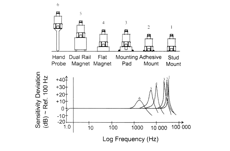
When mounting an accelerometer, there are several different options, each with their own pros and cons. In calibration, we typically stray towards the use of threaded studs or adhesives, but there are also flat magnetic, dual rail, hand probes, isolation bases and others. So why do we prefer to calibrate using stud mounting or adhesives? Take a look at the plot below; it shows the frequency response of an accelerometer using different mounting conditions.
 You
can see quite clearly that with increased thickness of material between the measurement surface (top of the reference accelerometer) and the test sensor, the mounted resonance of the sensor decreases. This plot represents one of the most common
issues in back-to-back accelerometer calibration: failing frequency response at high frequency. Added material between the reference sensor and the test sensor will cause the response to rise above the tolerance.
You
can see quite clearly that with increased thickness of material between the measurement surface (top of the reference accelerometer) and the test sensor, the mounted resonance of the sensor decreases. This plot represents one of the most common
issues in back-to-back accelerometer calibration: failing frequency response at high frequency. Added material between the reference sensor and the test sensor will cause the response to rise above the tolerance.
Stud mounting of an accelerometer is the preferred method for calibration, not only because it gives the best frequency response, but because stud mounting is most often how the sensor’s specifications were derived. Manufacturers want to represent the best case mounting condition for their product, so in order to check against their specifications, the same mounting condition should be used. The exception to this requirement occurs when a sensor is not calibrated to manufacturer specifications, but is characterized for a specific mounting condition. In this case, the mounting condition used in experimental testing is also used in calibration, regardless of the response. This allows test engineers to correlate real world response of their mounting condition to their data.
The change in frequency response with respect to the amount of material beneath the test sensor does not stop at adaptors. The quality (or lack thereof) of the mounting surface with respect to deep scratches, dents, dings and gouges also plays a part in the frequency response of the sensor. A common source of these problems can be dropping the sensor on a hard surface with corner impact. Though it may not break the sensor outright, plastic deformation at the corner can cause the sensor to no longer sit flush to a mounting surface, reducing frequency response. Leftover adhesive, even dirt and debris, can all contribute to sensor frequency response “failures." Inspecting and cleaning the mounting surface of the sensor should be a first step in any calibration procedure.
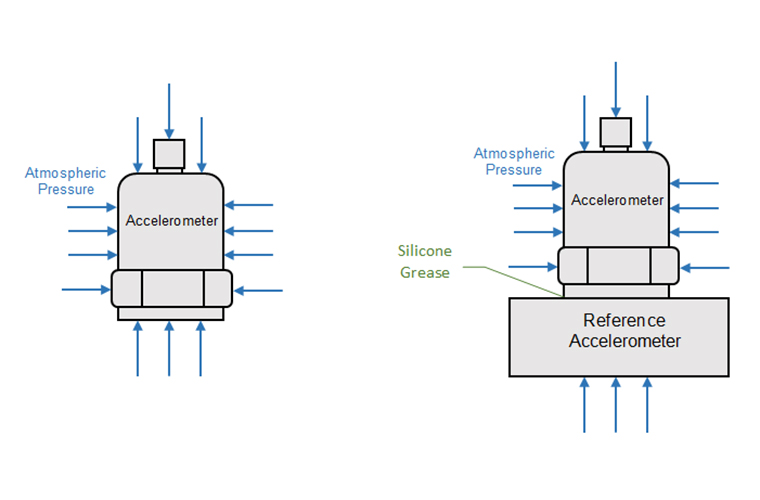 Another key requirement to accelerometer calibration is the use of a coupling grease between the reference and test accelerometers. This grease serves to fill in the voids between
the two surfaces to produce an airtight seal. The resulting effect is quite similar to the working phenomenon that allows a suction cup to adhere to a surface.
Another key requirement to accelerometer calibration is the use of a coupling grease between the reference and test accelerometers. This grease serves to fill in the voids between
the two surfaces to produce an airtight seal. The resulting effect is quite similar to the working phenomenon that allows a suction cup to adhere to a surface.
From the figure above, the left image shows an accelerometer (or any object) subjected to atmospheric pressure. The net sum force of this effect is zero, as pressure on each face is counteracted with an equal and opposite pressure on the opposing face. In the image to the right, grease is added with the accelerometer mounted to a reference, as in a back-to-back calibration configuration. With the grease filling the voids between the two sensors, atmospheric pressure acts only through the base of the reference accelerometer. Again, the net sum force of this effect is zero, but in this case this force is applied on the outer faces, applying a holding force between the reference and test accelerometers. This additional distributed holding force results in a flatter frequency response. It is even advantageous to apply grease between a sensor, adaptor and adaptor mounting face for isolation bases and magnetic mounts, and between the mounting face and adaptor for adhesive mounting.
Mounting torque can also play a role in calibration, though not as dramatic as some of the previously mentioned factors. The larger problem faced in both calibration and testing is stripped threads. Without the use of a torque wrench, stripped threads can be a recurring problem, especially with smaller 5-40 threads. Manufacturers typically supply torque specifications for a given thread size. Use them!
The last main cause for a “mounting” issue is the sensor cable itself. Though it could be a newsletter article of its own, the key point to cabling is the use of a strain relief loop through some form of cable fastening. On a calibrator, this typically takes the form of approximately 30 cm (12 in) of cable formed in a loop and fastened to the shaker. A neutral and controlled cable position allows for the reduction of connector strain effects and triboelectric effects (for charge output accelerometers) due to cable motion.
Beyond calibration laboratory metrologists, knowledge of mounting effects tends to thin out rather quickly, so feel free to share this article with your test and measurement colleagues.