Main Menu
- Home
- Product Finder
- Calibration Systems
- Calibration Services
- Digital Sensing
- Industrial Vibration Calibration
- Modal and Vibration Testing
- Non-Destructive Testing
- Sound & Vibration Rental Program
- Learn
- About Us
- Contact Us
A calibration laboratory was having a hard time calibrating a particular accelerometer. The sensor’s specification (according to the manufacturer’s) website indicated a sensitivity value of 100 mV/g (±10%) and a frequency response
up to 6500 Hz (±10%). The initial calibration results at the reference frequency (100 Hz) were good and a sensitivity value of 99.97 mV/g was measured (really close to the sensor’s nominal sensitivity). Surprisingly enough, the sensor
would repeatedly fail its frequency response calibration...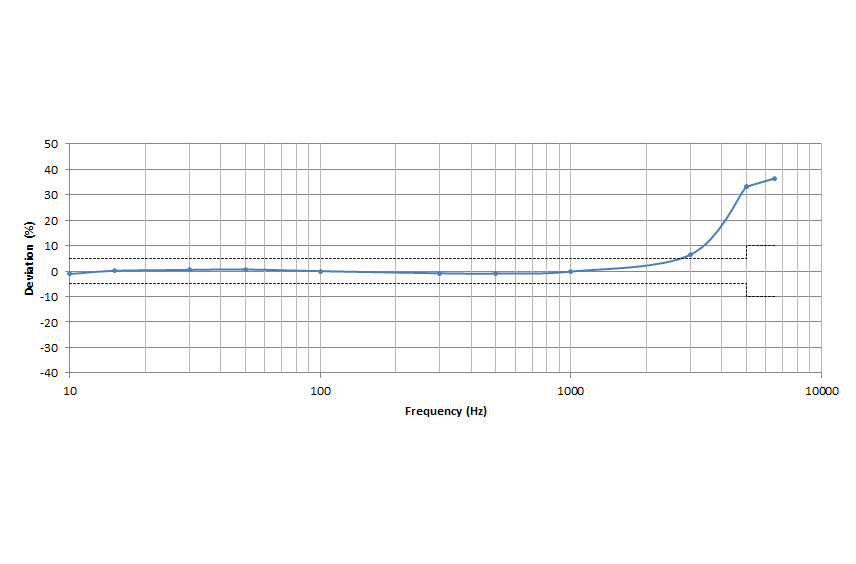 ...The calibration
results were within specifications for frequencies up to 1 kHz, but as the frequency increased, the discrepancies between the calibration results and the sensor's original calibration certificate would rise up to more than 36%. Why?
...The calibration
results were within specifications for frequencies up to 1 kHz, but as the frequency increased, the discrepancies between the calibration results and the sensor's original calibration certificate would rise up to more than 36%. Why?
The rise up on high frequencies was an indication of a possible mounting issue as sensor mounting resonance directly affects the practical upper frequency response of an accelerometer. So here we come to 3 basic rules related to good sensor calibration
mounting practices:
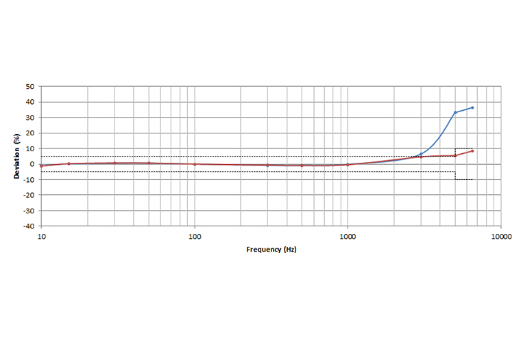
After following these 3 steps above, the sensor was recalibrated and the new frequency response showed deviation was reduced from 36% down to 8%. The sensor passed calibration without trouble! Here are the results before and after.
 It is amazing to see how mounting can affect a high frequency performance
of an accelerometer. Something as small as a piece of hair trapped between the sensor and the top of the shaker can similarly affect the high frequency response of the sensor. Well, we will leave this for another day, but if you want to try yourself
and send us the results, we can share it in a future edition of our newsletter!
It is amazing to see how mounting can affect a high frequency performance
of an accelerometer. Something as small as a piece of hair trapped between the sensor and the top of the shaker can similarly affect the high frequency response of the sensor. Well, we will leave this for another day, but if you want to try yourself
and send us the results, we can share it in a future edition of our newsletter!